Pushing Socket 7 to the Limit: Extreme Overclocking the K6-2 to 700 MHz and beyond!
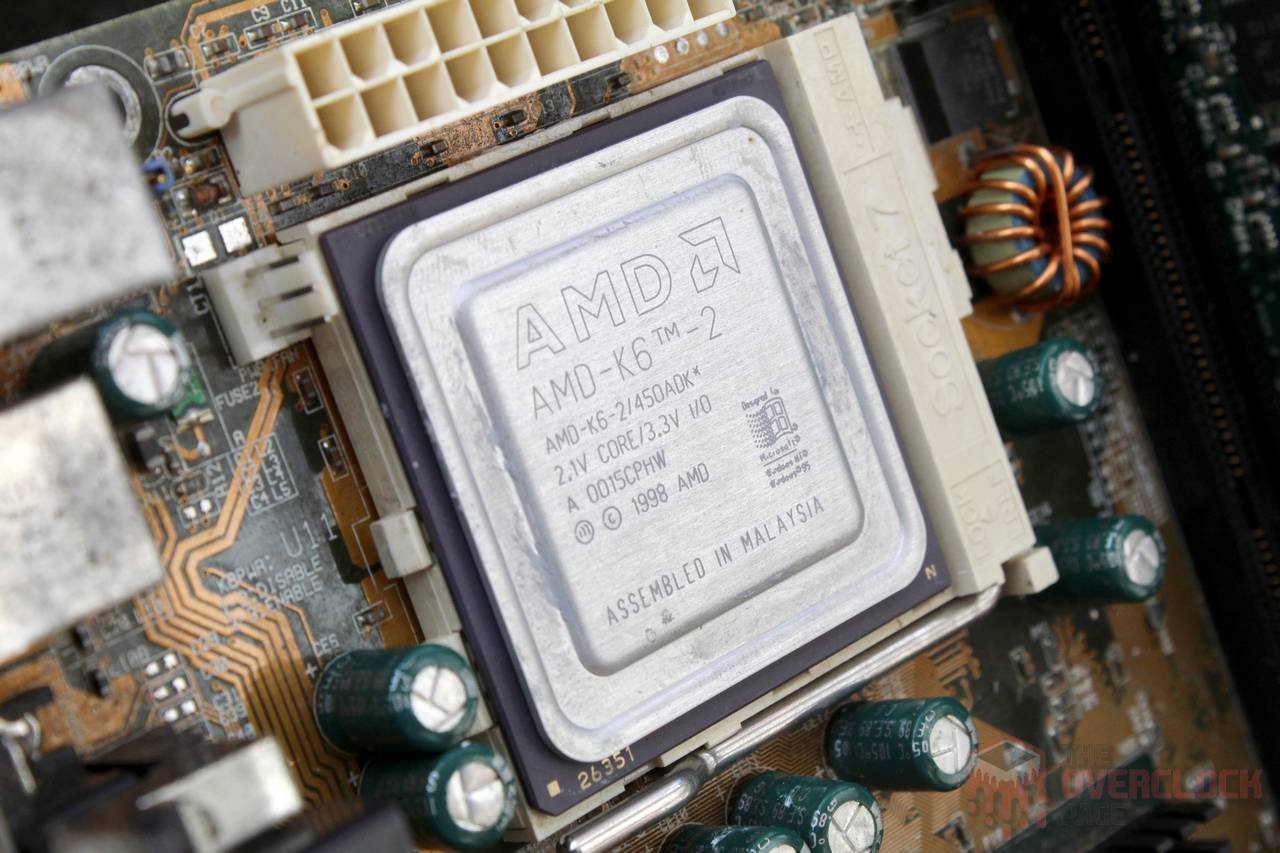
After a prolonged hiatus in articles about extreme overclocking, there is good news for those who enjoy this content. It’s back, and in a big way. The subject of this article is something quite special, the thing is capable of completing SuperPI 1M in just five minutes. It has also left a lasting impression on many people, whether positive or negative. Without further ado, we present to you: the AMD K6-2!
Introduced in 1998, this family of processors uses the Super Socket 7, a “plus” version of Socket 7 that enables operation with a 100 MHz FSB without overclocking. Furthermore, it supports higher frequency multipliers, up to 6X, and is also backward compatible with Socket 7 CPUs such as classic Pentiums, Pentium MMX, K6, and Cyrix.
The motherboard in question is an ASUS P5A rev1.03, which was also offered in a Baby AT version named P5A-B, with obvious differences in layout. Both models use the ALi Aladdin V chipset, which was considered the best-performing for this platform alongside the VIA MVP3.
There were several revisions of this motherboard, including the rare 1.06 version with 1 MB of L2 cache. However, the 1.03 version only has 512 Kb of L2 cache. It’s important to note that for this platform, only the K6-III, K6-2+, and the extremely rare K6-3+ included L2 cache on the processor die, with the other models relying on the relatively slow L2 cache included on the motherboard, which operates at the same frequency as the FSB.
It should be emphasized that the heatsinks on the chipset (north and south bridges) and cache were added later by the former owner of this motherboard. The P5A does not come with heatsinks as standard.
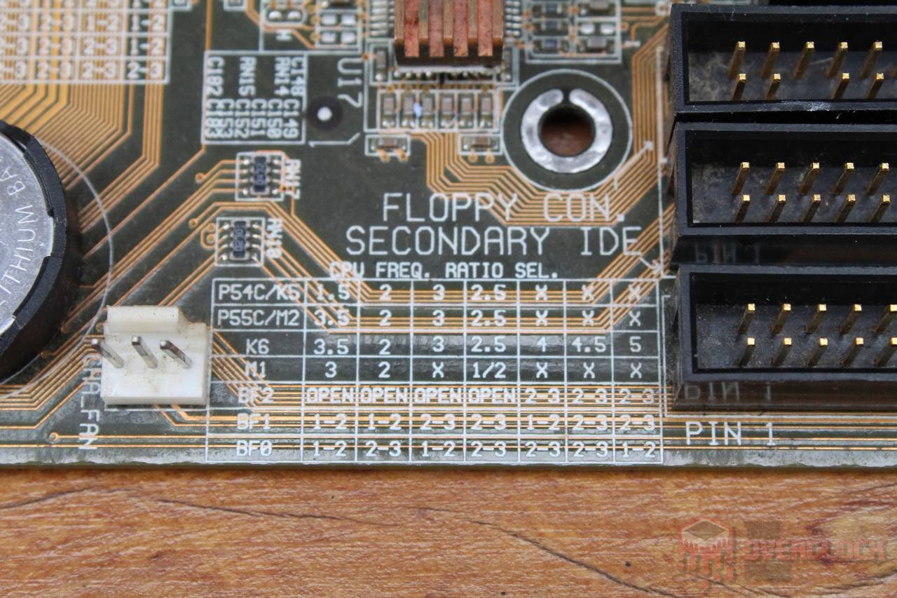
Another peculiarity of this era is that voltage and frequency adjustments were made through jumpers located on the motherboard, with the motherboard’s BIOS limited to memory timings and some other related (or unrelated) performance adjustments. To make things easier for the user, tables with the meaning of each jumper position were included in the board’s silk-screen printing by the manufacturer, which is very helpful when it comes to overclocking or adjusting for CPU upgrades.
The P5A allows for CPU voltage adjustment from 2V to 3.5V, where values above 3.2V are reserved for Pentium MMX, I/O voltage ranging from 3.3V to 4V, but with an OFFSET jumper that allows it to go up to nearly 5V, FSB ranging from 60 MHz to 120 MHz, but with the reminder that AGP/PCI frequencies increase along with it. Lastly, the multiplier ranges from 1.5X to 6X, with a small “cheat” for the K6-2 CPUs that make the CPU “interpret” the 1.5X and 2X adjustments as 5.5X and 6X, respectively.
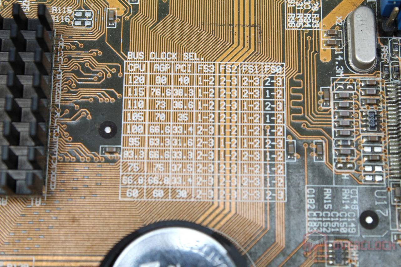

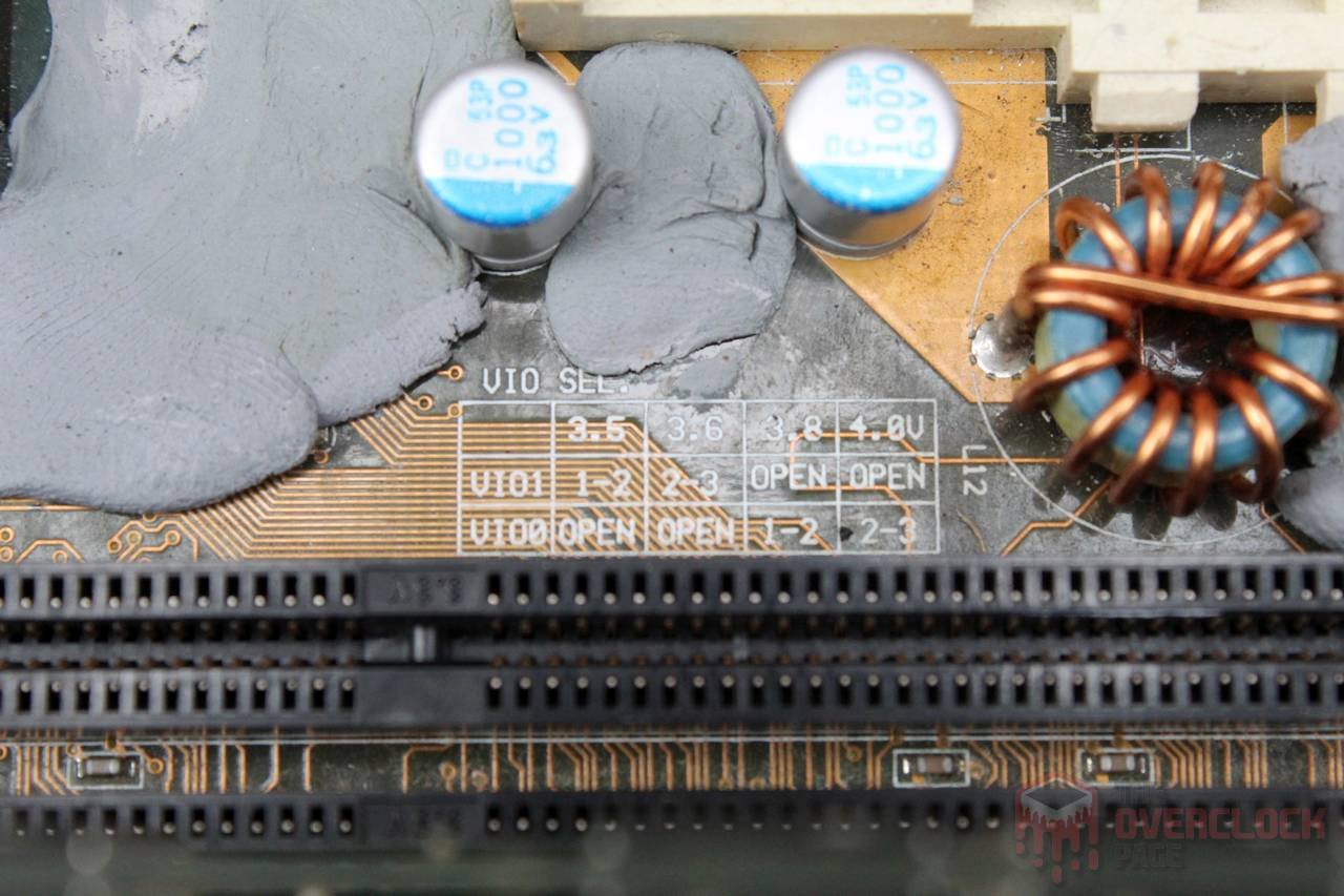
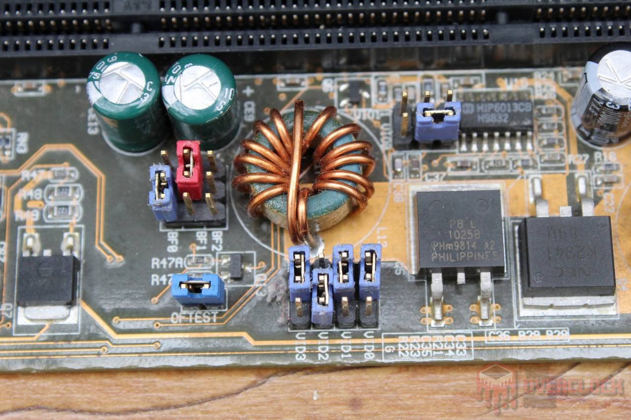
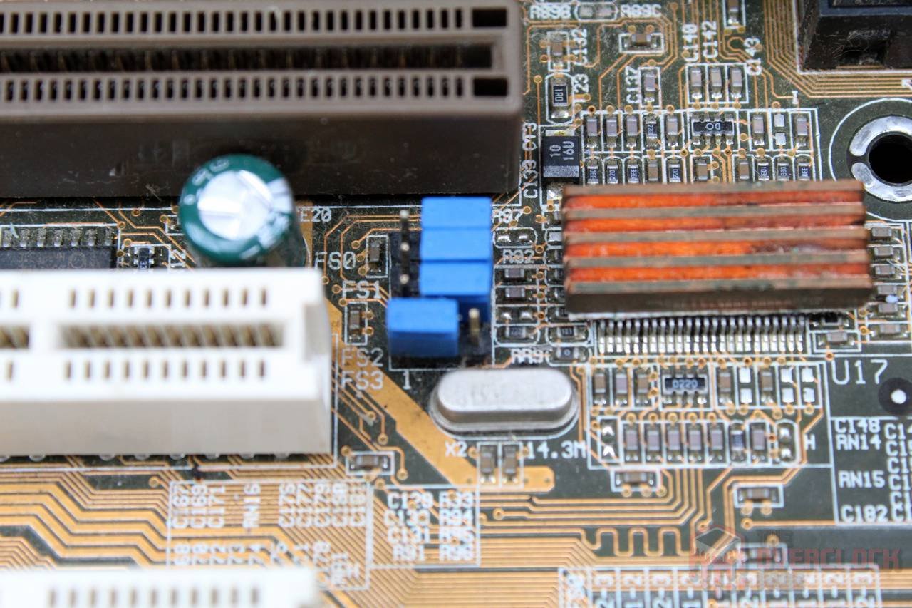
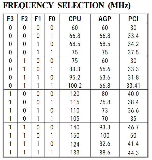
Regarding the FSB adjustment specifically, the PLL used in this motherboard, the PhaseLink PLL52C66-28, allows for several other FSB options besides those officially reported. When consulting the datasheet, there is a truth table with values up to 150 MHz. Interpreting this table is relatively simple: F3, F2, F1, and F0 are equivalent to the FS3, FS2, FS1, and FS0 signals on the board, where “1” corresponds to the jumper in the “1-2” position and “0” to the “2-3” position. As such, the board is indeed capable of functioning with these “extra” settings, but not always with stability, or even requiring the integrated L2 cache to be disabled, which is only viable from a performance standpoint if you are using a K6-2+, K6-3+ or K6-III, as in these models, the cache on the motherboard becomes L3.
The idea from the beginning was always to freeze this “vintage” platform to see how these old processors would behave. It’s worth noting that there was a first unsuccessful attempt, which ended with generalized instability when lowering the temperature and a corrupted operating system.
The first suspicions of this “reluctance” towards negative temperatures came from the power supply, after all, the Antec 1200W was used, which is much more modern than this motherboard, which is from a time when the +5V line was the most important and negative voltages were still used on buses such as ISA. However, replacing it with the “classic” Seventeam ST-350BKV made no difference.
Another suspicion came from the VRM capacitors, which despite being of renowned quality, manufactured by Sanyo, and performing well at room temperature, are components with more than 20 years of use. As we know, capacitors suffer from the “effects of time,” losing capacitance, gaining ESR, and to make matters worse, these old components, or even low-quality new ones, tend to deteriorate even further when exposed to drastically negative temperatures. So, I went in search of new solid capacitors of 1000uF 6.3V to replace them, finding those manufactured by NCC, Nippon Chemi-Con, which are of very good quality!


It is important to note that replacing old capacitors with modern ones is not always a simple task, as linear regulator circuits (LDO) can become unstable with the much lower ESR of modern components, which can certainly cause problems. In the case of the ASUS P5A, it already uses Buck DC-DC converters and although it only has one phase, it works similarly to VRM circuits found on modern motherboards, rarely presenting instability problems due to much lower ESR, although this is also possible.
In any case, if you are going to make this type of repair or modification to vintage hardware, do your research and do it with great care, after all, these parts have become increasingly rare (and expensive) and of course, I am not responsible for any losses in case you attempt to replicate what was done here. 😉
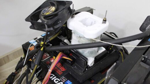
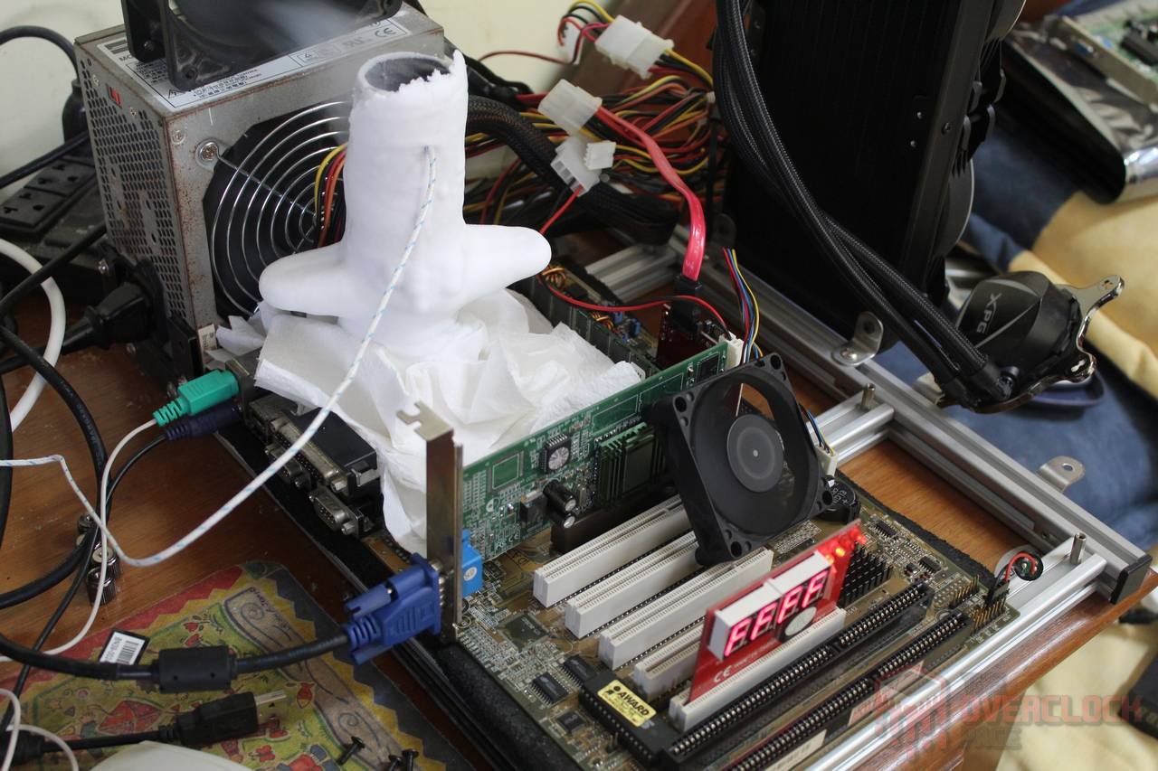
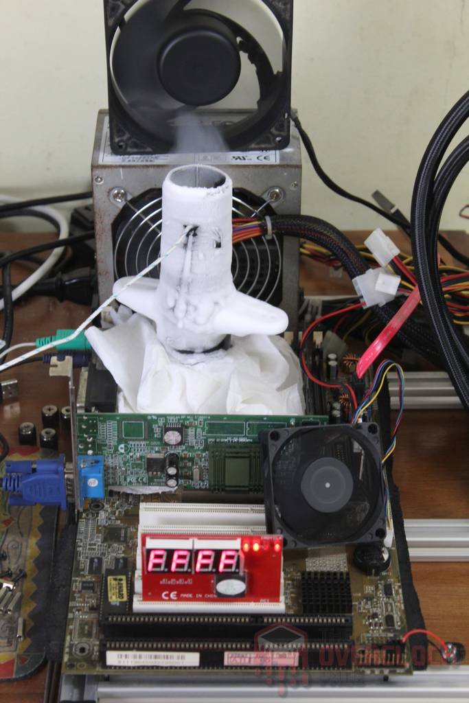
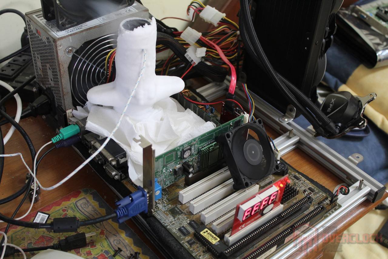
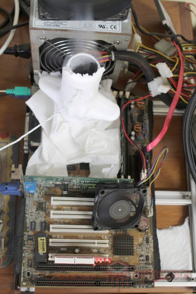
Due to the “exotic” layout of this motherboard, where the 20-pin ATX power connector is located virtually “glued” to the CPU socket, using a pot like the SF3D Inflection Point is basically impossible, so it was necessary to resort to a chipset pot, manufactured by Ian Melo using a copper base from an “Intel cooler box” soldered to a metal tube of the same diameter. Although it may seem insufficient, it is reasonable to put into perspective that a K6-2 500 has a maximum TDP of 20W and a typical one of just over 12W, which is less than that of the X38/X48 chipsets for which this pot was designed.

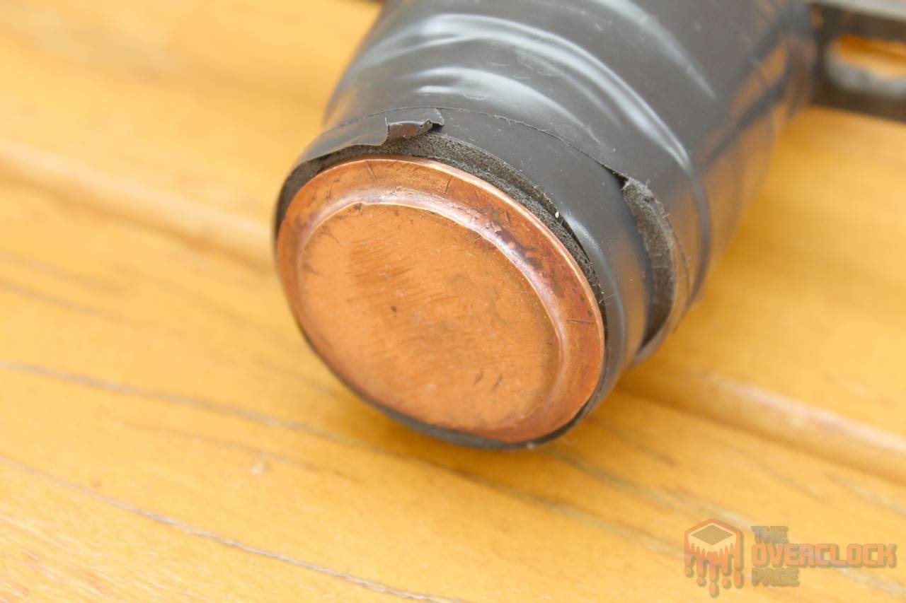
The motherboard was insulated using clean-type rubber and paper towels, which proved to be perfectly suitable during the Extreme OC session.
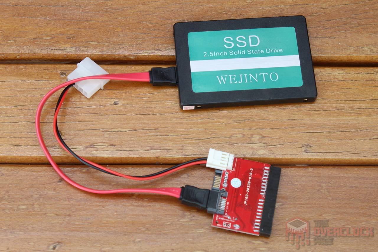
In addition to all the preparation for Extreme OC, an IDE PATA to SATA adapter was used for installing the operating system, which allows the use of modern SSDs on these old platforms. Of course, there are some limitations regarding the size of the SSD, often requiring creating a much smaller partition than the SSD’s capacity. However, there is no doubt that this is still a much better solution than using an old (and slow) hard drive. 🙂
Hardware used:
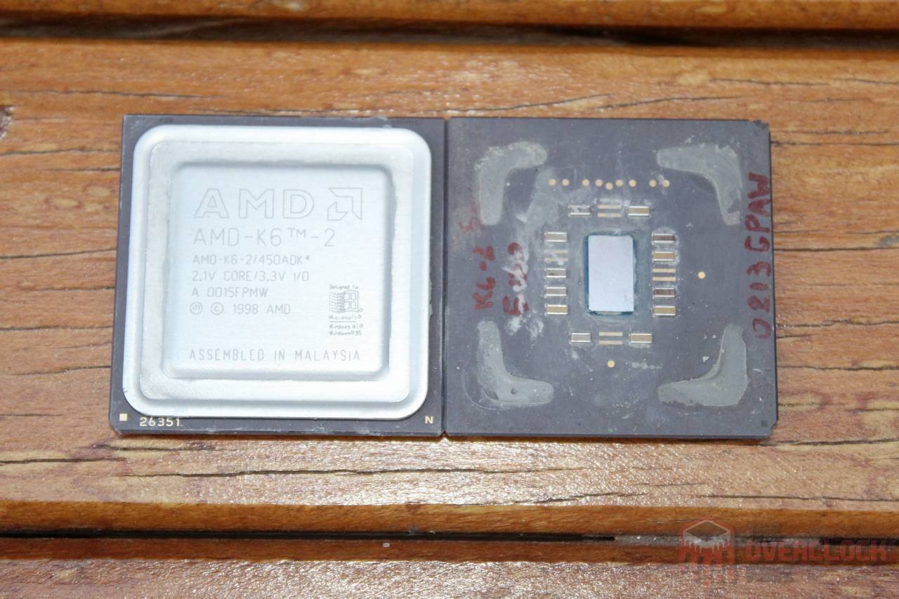
CPU:AMD K6-2 450MHz 0015FPMW
MOBO: ASUS P5A rev1.03
RAM: 256 MB SDRAM Corsair PC-150
GPU: Pine SiS 305 32 MB
PSU: Seventeam ST-350BKV
COOLER: Pot de chipset by Ian Melo + LN2
SSD: Weijinto 256 GB
Software: Windows XP SP3, Super PI 1.5 XS, wPrime 1.55, PiFast
Objective of the tests:
The objective is to discover the limit of the old K6-2 450MHz processor in extreme overclocking, observe how the platform behaves when subjected to extreme cold, and ultimately attempt to achieve the top ranking.
Results:
Due to the fact that this is an old platform whose parts are no longer easy to find, it is a good idea to be cautious. Starting with a stable setting at ambient temperature (115*5 2.6V and Vio at 4V), liquid nitrogen was gradually added while paying attention to possible issues caused by CB or CBB. Surprisingly, there were no problems even with “full pot,” or -195?°C, which is excellent. After all, among the few reports of people who have ventured into extreme overclocking on this platform, cold bug seems to be a reasonably common occurrence.
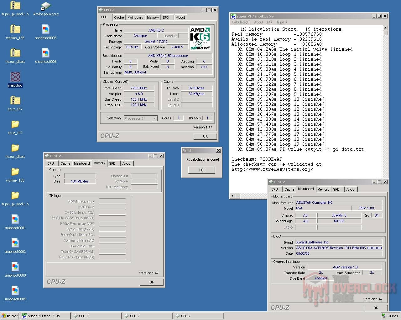
Knowing this, the next step was to increase the CPU frequency. The first step was to set the multiplier to 6X, resulting in 690 MHz at 2.6V, but with disappointing results in SuperPI 1M and Pifast, which are highly dependent on memory performance. Therefore, they tend to show greater gains with overclocking on the FSB than on the CPU. The next step was to increase the FSB to 120MHz, resulting in an incredible 720 MHz on the CPU and good results!
The next step would have been to set the FSB to 124MHz and reach 744 MHz with the K6-2. However, instabilities began to appear, and the first idea to try was the most obvious: to increase the vcore of the processor. However, this only worsened the problem. Upon further testing, it was concluded that this particular sample does not work well with more than 2.6V, showing better results, including in benchmarks, with something between 2.4V and 2.5V. Another detail is that this may be the limit of the motherboard, more precisely the L2 cache, which is not 100% stable with an FSB above 120MHz, even when setting Vio to almost 5V.
Despite this, it was possible to complete PI 1M with 744 MHz (124*6). However, the time ended up being slightly worse than with 720 MHz, so this ended up being the “practical” limit of this session.
Regarding the obtained results, well, we are talking about hardware from the last millennium, right? So taking just over 5 minutes to complete Super PI 1M, 8 minutes for wPrime, and over 9 for Pifast may seem like a lot, but these are second and first places, respectively, in the K6-2 450 ranking.

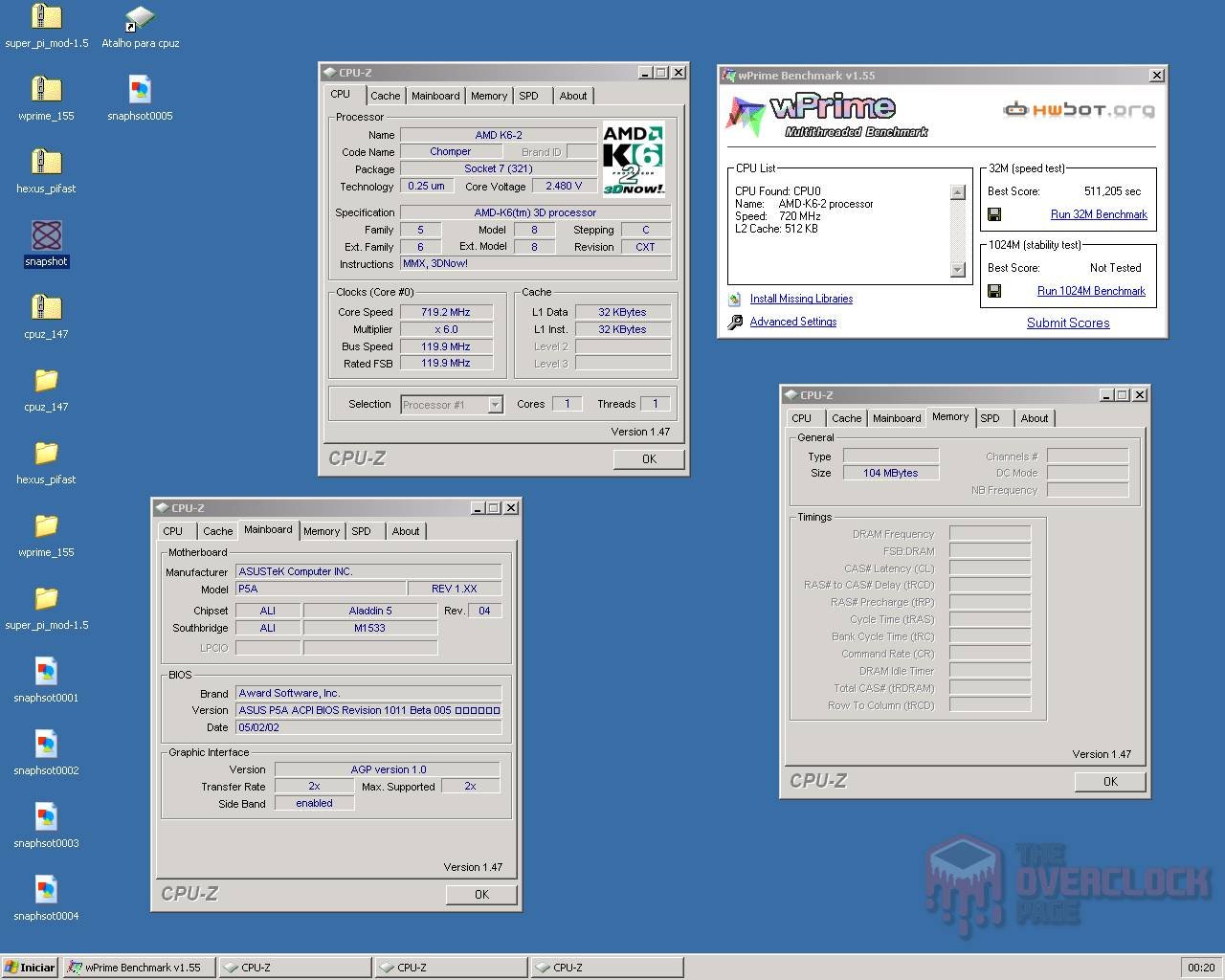
Unfortunately, CPU-Z has issues detecting the FSB on some motherboards with Aladdin V chipset, such as the ASUS P5A. Therefore, it was not possible to validate the maximum frequency. However, to make it worthwhile, here’s a screenshot of the screen during the post running at 744 MHz! 😀
And finally, the traditional gallery of frozen hardware photos, something that cannot be missed in an article about extreme overclocking!



Conclusion:
Extreme overclocking is definitely an interesting “hobby,” especially when it involves “different” hardware, whether it’s something very recent in the market, challenging, or in this case, very old!
Both the K6-2 450MHz and ASUS P5A survived the extreme overclocking session, working well even at temperatures around -195ºC, or “full pot,” as we usually call it, without presenting CB or CBB. This sample of K6-2 450MHz did not work well with voltages above 2.6V, presenting slightly better performance using voltages between 2.4V and 2.5V.
Regarding the achieved frequencies, it was possible to reach 744 MHz (124*6) with 2.6V, although with instability due to the relatively high FSB, so the benchmarks passed with “only” 720 MHz, which is remarkable for the old K6-2. From the results, it was possible to achieve two first places and one second in the K6-2 450 ranking, which is excellent!

